 If the above-knee amputee is to have a normal appearance while walking, the prosthesis must have a knee joint that will not buckle as he rolls over the artificial foot during the stance phase of walking.
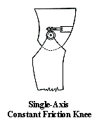
The simplest way to achieve this is to use mechanical friction about a bolt that connects the socket (thigh) to the shank. The bolt is located behind the path of the weight of the body to the floor so that it will not buckle when the user is standing straight. The mechanical friction, which may be a simple adjustable brake, keeps the shank from swinging forward too fast as the user swings the artificial leg through to the next step. The chief limitation in the single-axis, constant friction design is that appearance is normal at only one speed of walking for a given setting of friction, The amputee must be very careful in walking, especially on uneven surfaces, to avoid stumbling.
 A great deal of effort has been spent over the Years developing knee systems which overcome the limitations of the single-axis, constant friction knee. Many designers have been successful to some degree, but because of the simplicity of the constant friction design, no new system has totally displaced
it.
A great deal of effort has been spent over the Years developing knee systems which overcome the limitations of the single-axis, constant friction knee. Many designers have been successful to some degree, but because of the simplicity of the constant friction design, no new system has totally displaced
it.
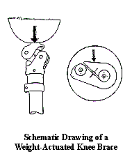
Weight Actuated Knee Brake
The second level of complexity in knee systems is the use of a weight-actuated brake with constant friction. Two bolts are used at the knee, so that when one pivots about the other when the amputee is standing, the force of the body weight engages a brake that keeps the knee from buckling.
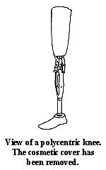 Polycentric Knees
To provide better control of the above-knee prosthesis during standing and the stance phase of walking than can be provided with a single axis knee, designers have used mechanical linkages between the socket and shank that, in effect provide for a moving center of rotation. Such designs are known as polycentric knees. Used originally for the knee-disarticulation case, polycentric knees now also used in prostheses for higher levels, especially when stability at heel strike is desirable. The swing phase control may be either mechanical friction or hydraulic resistance. The one limitation of the polycentric design is that range of motion about the knee may be restricted to some degree but not enough for it to be objectionable to most users.
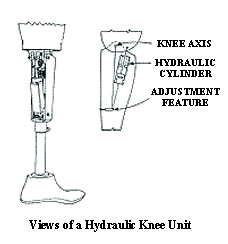 Hydraulic Knees
To allow the amputee to vary his speed of walking, a number of hydraulic devices are available. In the simplest system, the piston is attached to a pivot in the thigh section of the prosthesis behind the knee bolt, and the cylinder is attached to a pivot in the shank. Because of the way oil acts when forced through a small hole the amount of resistance required for a given velocity of walking is provided automatically.
The most complex knee systems of those available are those which control of both swing and stance phase with a single hydraulic cylinder. Braking of the knee is brought about automatically when the knee begins to buckle, without interfering with normal flexion and extension of the knee. The same system permits the velocity of walking to be varied at will. These features are appreciated most by very active amputees.
The prescription for the prosthesis is based on activity level and particular needs of each amputee.
Go to next section
Go to previous section
Go to Table of Contents
Copyright 1996 - Alvin L. Muilenburg and A. Bennett Wilson, jr.